These resources are for makers who wish to make one or more PX4 Horticulture Controller project components themselves. This maker manifest includes summary manufacture instructions and a list of specialty tools required for each major component.
Project Resources
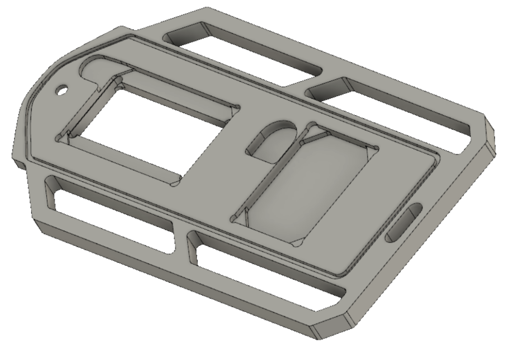
- Project enclosure model: Front Face
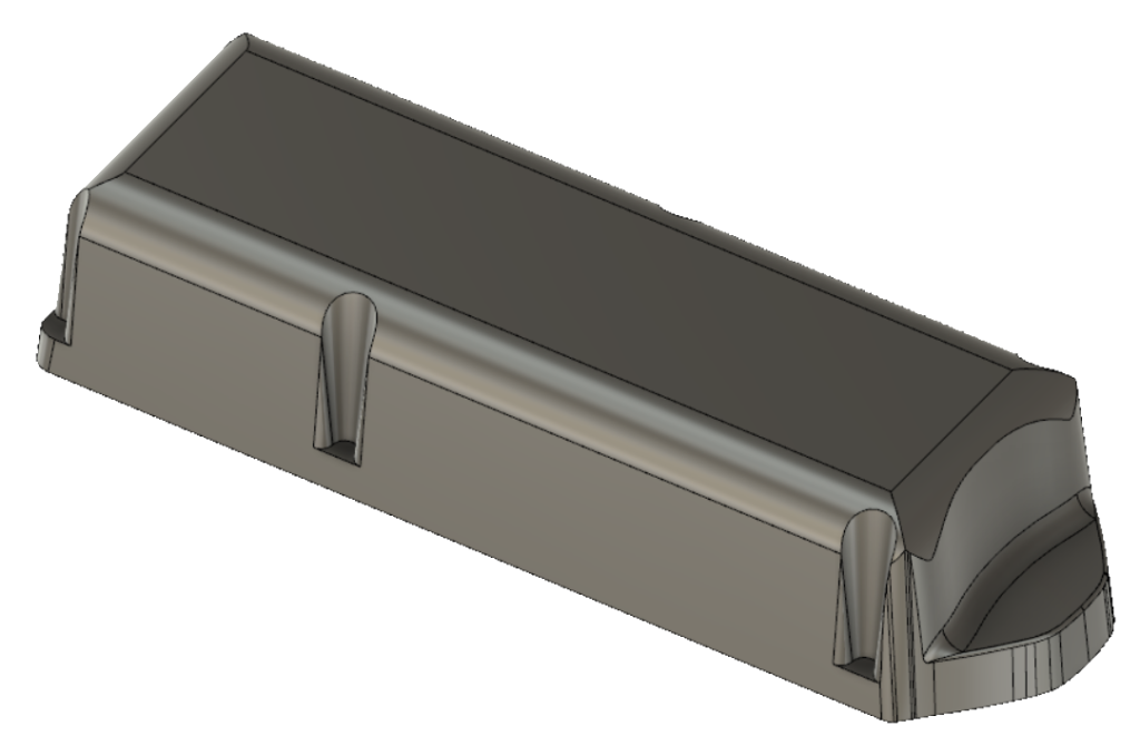
- Project enclosure model: Rear Shell Mould
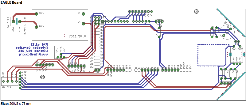
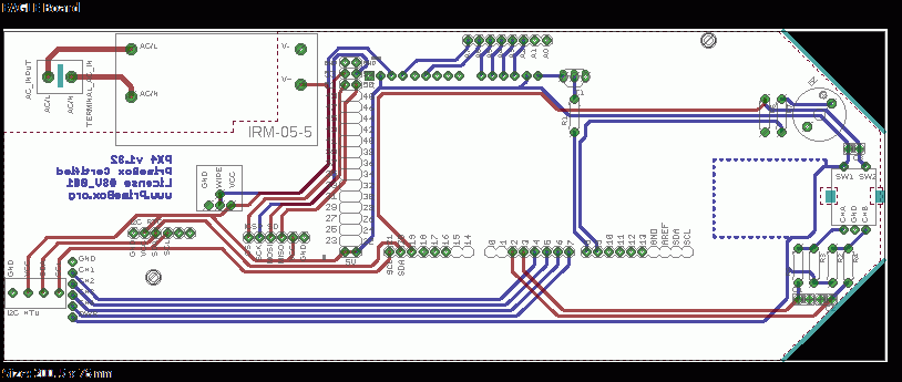
- PCB design files
- Controller firmware repository
- Complete project Bill of Materials
Please use caution when assembling high voltage electrical components. Bridging improper electrical connections can result in injury or death – do not attempt to build this project yourself unless you’re familiar with how to avoid accidental shock.
Project Component Manufacture and Assembly
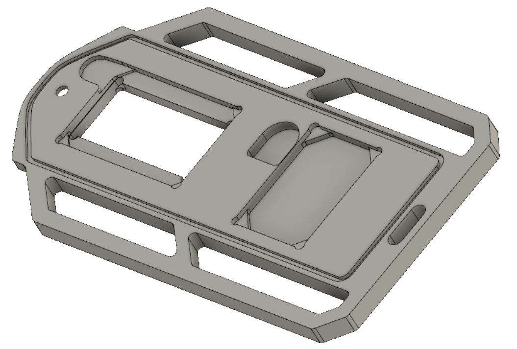
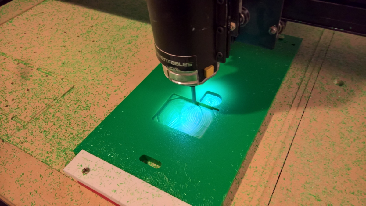
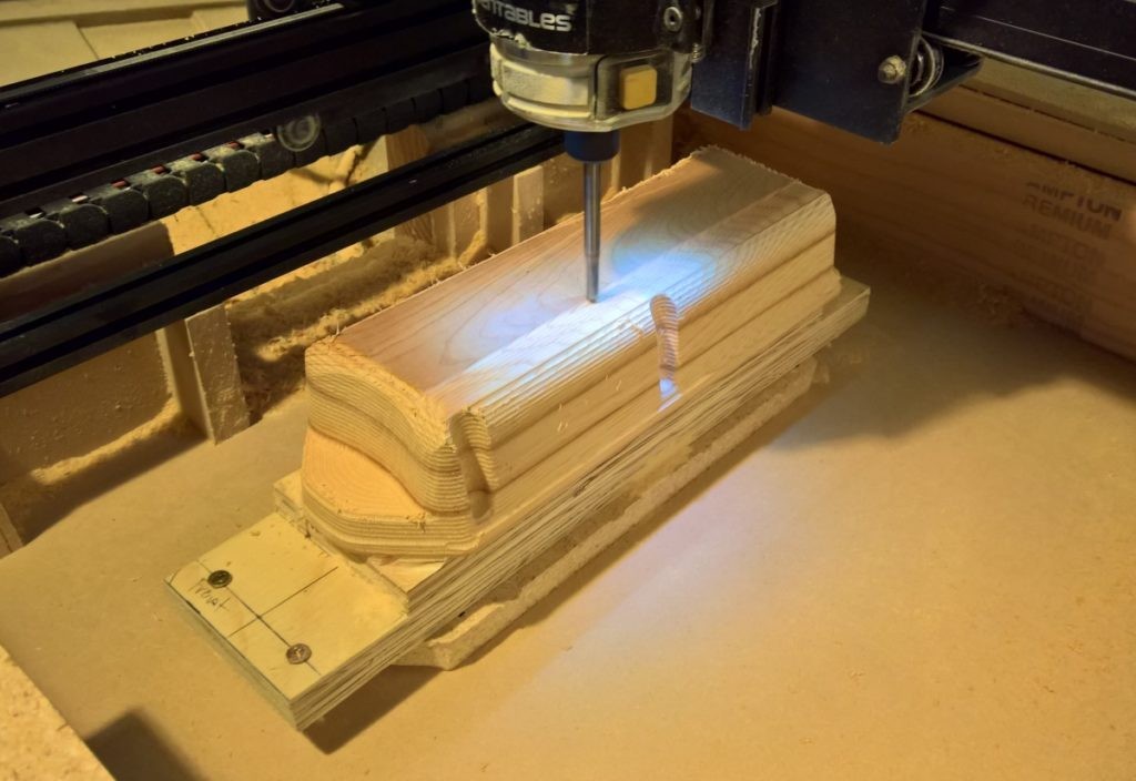
Front Face
Use your CAM solution of choice to create toolpath operations for the step file included in this project. It’s recommended to use a ½” O-flute endmill but smaller endmills will work. If not using a vacuum table ensure your clamp fixtures clear the cutter and tabs are used for any pieces that need to remain secured during the job. Notice the model has pockets on both sides. Consider using registration pins to align the piece when milling the piece.
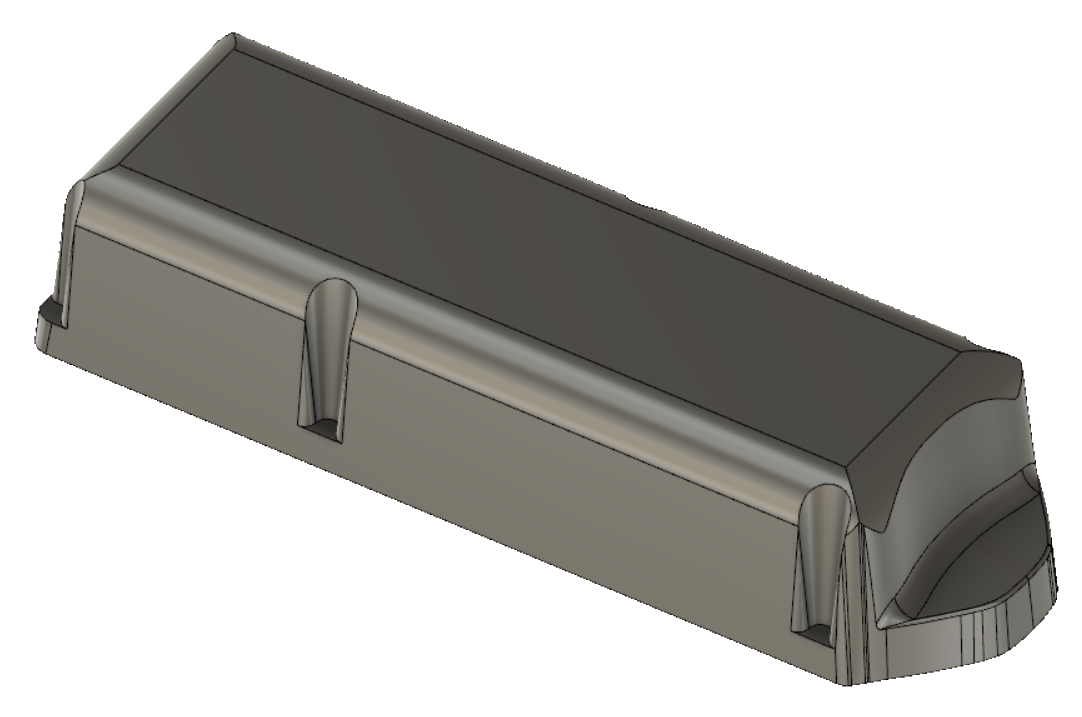
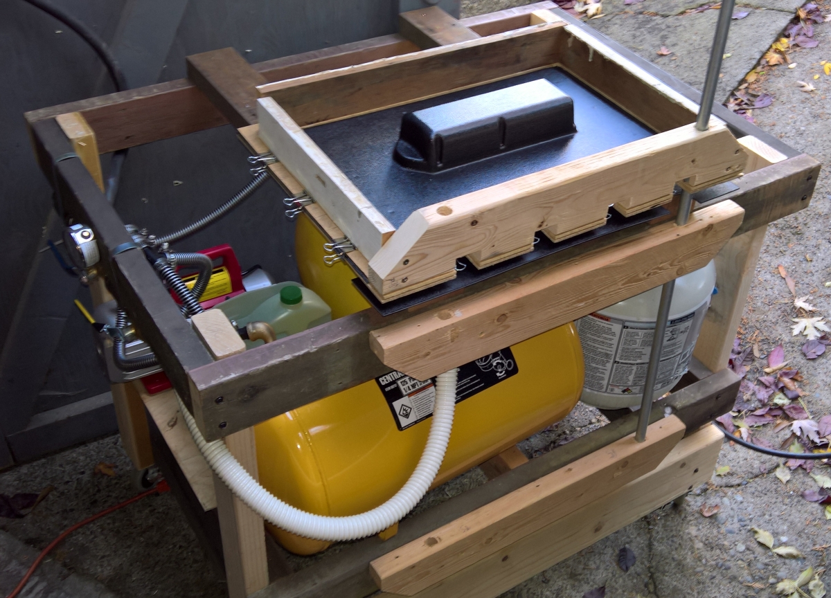
Rear Enclosure
The rear enclosure is formed from ABS sheet stock on a vacuum former. Ensure that the thermoformer you plan to use is capable of forming material 12”x24” in size. Begin by first milling the mold on a CNC machine using the step file published in this project. Unless you’re cutting the mold as layers and assembling later, ensure your CNC/endmill combination has a LOC greater than 2.25”. Once the rear enclosure assembly is formed, trim it from its flashing and drill through holes for fasteners in the fastener cavities.
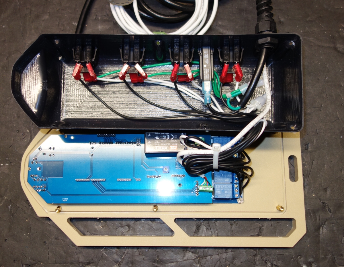
Internal Electronics
Begin by mounting the LCD and relay module to the front face with shallow screws. Next, assemble the PCB using the eagle files attached to this project. Double check component placing as through-hole components can be affixed to either side of the board in most cases – resulting in internal spacing that prohibits closing the enclosure completely. Once the board is ready, fit it onto the LCD and relay module pins. Also remember to affix the post nut to the encoder from the front of the device.
Component Wire-up
Cut the harness components first, securely crimping each connector before installing the harness. Run load wires from the outlets to the relay module making sure there’s enough slack to place the rear enclosure and the front face next to one another on a flat work surface. Run a single neutral lead from the rear enclosure to the AC power terminal on the backplane PCB. terminate each of the relay module inputs with a single 14-gauge wire running to the resettable short circuit fuse in the rear enclosure. Once all of the primary wire has been run between the front face and rear enclosure assemblies, run the AC cord into the rear enclosure through the PG9 stress-relief gland. Connect the main line AV load wire to the empty fuse terminal and connect the neutral and ground to their respective terminal caps.
